Julius Ssimbwa , Seok-Hyun Yoon , Yeongrok Lee and Young-Chai Ko
Towards 5G-Advanced NR-Unlicensed Systems: Physical Layer Design and Performance
Abstract: In the pursuit of a highly reliable and low-latencyenabled 5G-advanced new radio unlicensed (NR-U) system, addressing the challenge of high error rates and high signaling overhead transmissions remains key to improving network performance. In this context, to reduce error rates, mechanisms such as retransmissions can be employed. However, performing multiple retransmissions comes at the cost of utilizing extra transmission resources, which in turn affects the spectral efficiency of the network. This would further necessitate proper scheduling to alleviate resource wastage and undesirable collisions during data transmission. In this article, we provide an overview of the design specifications of the long-term evolution-license assisted access (LTE-LAA) technology and the prospective enhancements to enable NR-U operation in bands beyond 7 GHz. Additionally, we examine the configurations of selected design features to enable NR-U scheduling. Specifically, we illustrate the benefits and the limitations of the choice of the switching pattern under the frame structure, the feedback value type under the hybrid automatic repeat request (HARQ) procedure, and the timing parameters under the radio link control (RLC) layer. Besides, we present simulation results to depict the impact of the configurations mentioned above on the performance of NR-U.
Keywords: Coexistence , high reliability and low-latency , new radio unlicensed , NR-U scheduling , unlicensed band
I. INTRODUCTION
WITH the expeditious development of powerful data processing-capable handheld mobile devices, network operators have been compelled to scramble for the unlicensed spectrum to support the resulting data traffic demands. Fortunately, the federal communications commission (FCC) has availed more bandwidth in the unlicensed spectrum to accommodate more radio access technologies (RATs) such as 5G new radio unlicensed (NR-U), thereby presenting an opportunistic platform for offloading traffic to extend capacity and improve coverage [1]–[4]. In this article, attention is directed towards 5G NR-U, whose features were developed with inspiration from the 5G technology [5]. The benefit of operating in the unlicensed band lies in the increased data rates and capacity in the presence of wider bandwidth. However, the coexistence among RATs presents a greater concern due to the disparity in their design specifications. Moreover, unregulated operational procedures could result in the wastage of resources and undesirable interference leading to the degradation of system performance. Furthermore, operating in the unlicensed spectrum makes the network user vulnerable to experiencing services of unreliable quality with high latency and low reliability [6]. It is therefore beneficial to investigate the spectrum usage and network product design to ensure an amicable coexistence environment among unlicensed spectrum-occupying RATs and improve the quality of service (QoS).
A. Related Works
Related works by both industry and academia indicate that various investigations, in the form of analytical modeling and experiments, are in progress to attain efficient spectrumsharing techniques, spearheaded by several bodies such as 3GPP and IEEE 802.11 [7], [8]. In [9], the authors discuss challenges and potential solutions and perform simulation evaluations for the channel access procedure based on beam transmissions to ensure the coexistence of NR-U systems among different RATs in millimeter wave (mmWave) bands. A survey discussing opportunities and challenges in designing NR-U features for the coexistence of Wi-Fi and 5G NR-U in the 6 GHz bands is presented in [10]. The authors in [11] study the coexistence between Wi-Fi and 5G NR-U systems by conducting simulations and evaluating results in terms of delay and throughput. In [12], the authors propose a scheme to cope with continuous channel access failures for uplink control transmissions and improve the latency and reliability of cellular networks in unlicensed spectrum. The authors in [13] build an NR-U system-level simulator to evaluate several aspects such as numerology and channel access procedure, for the coexistence of NR-U and IEEE 802.11 technologies in mmWave bands. References [14] and [15] suggest resource management schemes related to time, bandwidth, and power allocation to ensure the harmonious coexistence of NR-U systems with the incumbent Wi-Fi systems.
B. Motivation and Contributions
While several authors provide different perceptions on improving spectrum usage as shown by the extensive studies on NR and long-term evolution (LTE) operation in the unlicensed bands, more explorations on advanced NR-U systems for operation in bands beyond 7 GHz will be required. In this article, motivated by the inter-RAT coexistence concerns in conjunction with the scarcity of spectrum resources resulting from the demand for massive connectivity and high data traffic, we study the performance of NR-U under varying configurations of the design features. Moreover, the disparity in the design of NR-U and other RATs, say Wi-Fi, renders it more aggressive when contending for the channel with Wi- Fi, resulting in deterioration of Wi-Fi performance. Besides, to guarantee fairness in channel access, it is recommended that the impact of NR-U on an existing Wi-Fi system should not be more than the impact of another Wi-Fi system on the existing Wi-Fi system [16]. We also derive motivation from the need to achieve high reliability and low latency in the next generation of NR-U systems. It is worth mentioning that contained herein is the current and ongoing NR-U work. We summarize our contributions in this article as follows.
· We briefly discuss various transmission protocols of long-term evolution-license-assisted access (LTE-LAA) and NR-U. Particularly, we compare the physical layer design of LTE-LAA and NR-U, including channel access, signal detection, and others. Furthermore, we review the operating features of NR-U for frequency bands up to 7 GHz and above, respectively.
· We examine the configurations of selected design features to enable NR-U scheduling. We share design rationales comprising the frame structure, the hybrid automatic repeat request (HARQ) procedure, and the radio link control (RLC) layer.
· We present simulation results to provide a comprehensive understanding of the benefits and limitations of different configurations associated with the switching patterns, HARQ feedback value type, and the RLC layer timing parameters, on the performance of NR-U. The results indicate that an appropriate configuration can improve performance in terms of high reliability and low latency.
The remainder of this article is organized as follows. In Section II, we provide a brief background about LTE-LAA and NR-U and their corresponding features. Next, we present investigations on the configurations for selected NR-U design features in Section III, backed up by a couple of simulations in Section IV. We then conclude this article in the final section.
II. LTE-LAA AND NR-U OVERVIEW
A. LTE-LAA Key Functional Features
The legacy LTE-LAA was designed to operate in four main deployment scenarios based on carrier aggregation under licensed and unlicensed bands. Carrier aggregation involves communication between the user equipment (UE) and a single cell, say primary cell (Pcell), through two or more contiguous or non-contiguous component carriers. The defined deployment scenarios may include scenario 1, which consists of carrier aggregation between a licensed macro cell and an unlicensed small cell, scenario 2, characterized by carrier aggregation between a licensed small cell and an unlicensed small cell without macro cell coverage, among others [3]. The operation of LTE-LAA was originally supported as a supplemental downlink (DL) secondary cell (Scell) only, aided by a licensed Pcell through carrier aggregation. Nonetheless, the enhancements in LTE-LAA, say enhanced-LAA (eLAA) and further enhanced-LAA (feLAA) in Rel. 14 and 15, paved the way to supporting uplink (UL) transmissions as well. We highlight some of the peculiar features of a generic LTE-LAA system as follows.
· Channel access scheme: Before accessing the channel, LTE-LAA-enabled systems are required to perform Listen-before-talk (LBT), a process that involves a clear channel assessment (CCA) to determine whether it is busy or idle. Transmission can only be guaranteed if the channel is idle, otherwise, several CCAs are performed depending on the specified type of LBT category (CATx-LBT) [3], ranging from CAT1-LBT, in which no LBT is performed, to CAT4-LBT where LBT is done alongside random back-off with a variable contention window (CW). In other categories, LBT is done with random back-off with a fixed CW size or without random back-off.
· Detection of LTE-LAA and other RATs’ signals: During spectrum sensing, the device uses a mechanism called energy detection (ED), which involves measuring the energy in the detected wireless signal and comparing it with a predetermined ED threshold, say -72dBm. If the measured energy is less than the ED threshold, the channel is considered idle, otherwise, transmission cannot take place since the channel is busy. This prompts the device to execute CCA for an extended period of time while comparing the detected energy level with the ED threshold until channel access is obtained.
· Channel occupancy structure: Once the channel access is secured, the device can only transmit for a specified period known as channel occupancy time (COT), which depends on the channel access priority class (CAPC). For instance, the maximum channel occupancy time (MCOT) of devices categorized under CAPC 3 or 4 is specified as 8 ms. Nonetheless, when the absence of any other RAT sharing the carrier on a long-term basis is guaranteed, it is specified as 10 ms [17].
B. NR-U Key Operating Features for Bands up to 7 GHz
Contrary to LTE-LAA whose deployment was done in the 5 GHz (5150–5925 MHz) unlicensed spectrum, NR-U considers roll-out in 5 GHz and beyond, including bands up to 7 GHz and 60 GHz [3], [4]. In addition to carrier aggregation, NR-U supports dual connectivity and standalone modes. Dual connectivity constitutes a UE communicating with several Pcells and Scells. The standalone application allows operation in the unlicensed band only, without support from the licensed network. The five NR-U deployment scenarios are outlined below.
· Scenario A: It is characterized by carrier aggregation between a licensed band NR Pcell and an unlicensed NRU Scell.
· Scenario B: It involves dual connectivity between a licensed band LTE Pcell and an unlicensed NR-U PScell.
· Scenario C: It is standalone.
· Scenario D: It constitutes an NR Cell with UL in the licensed band and DL in the unlicensed band.
· Scenario E: It involves dual connectivity between a licensed band NR Pcell and an NR-U PScell.
We concisely summarize some of the design features of NR-U as follows.
· Channel access and detection of wireless signals: The conventional LBT procedure, including the CW adjustment, and the ED-based mechanism in LTE-LAA will be adopted for carrier sensing in NR-U. Besides, gNB or UE can utilize CAT4-LBT to initiate COT for usual data transmissions. On the contrary, gNB can deploy CAT2-LBT to perform transmissions for the discovery reference signal (DRS) to enable UE to detect an active channel. Despite ED being an easy scheme to implement, several system designers have shown interest in the use of preamble detection (PD) or hybrid (ED and PD) signal detection for advanced NR-U systems to enhance reliability, power efficiency, and so forth [4]. PD involves the transmission and the detection of a well-known preamble signal, whose energy is compared with a pre-determined PD threshold. If the energy level is less compared to the PD threshold, the channel is idle, and the reverse is true. Before adopting PD or hybrid ED and PD, the issues concerning reliability, detection/decoding complexity, and power consumption need attention.
· Random access channel (RACH) procedure: Unlike the legacy LTE-LAA which supports a contention-free RACH procedure [3], NR-U targets both the contentionfree and contention-based random-access schemes. For the contention-free RACH, gNB controls the access by assigning the dedicated preambles to each UE, while in the case of contention-based RACH, each UE randomly chooses a preamble to establish a link with gNB. Owing to the possibility that several devices can select the same preamble, contention resolution is required. Therefore, instead of a 4-step messaging (Msg) RACH, which can elevate the delay even more alongside accumulated LBT failures, leading to reduced transmission opportunities, a 2-step RACH has been identified as a potential remedy to minimize random access delay and overhead [4]. Simply put, the conventional 4-RACH procedure, constituting the random access preamble (Msg1), random access response (Msg2), scheduled transmission (Msg3), and contention resolution (Msg4), is compressed to the 2-step approach made up of combined Msg1 and Msg3, and combined Msg2 and Msg4.
· Scalable subcarrier spacing (SCS) and wideband operation: LTE-LAA operation is specified under 20 MHz bandwidth whereas NR-U targets a much wider bandwidth with flexible SCS options to allow the efficient use of resources with lower control overhead. The alternatives of SCS such as 15 kHz and 30 kHz, will enable support for operation in bands below 6 GHz while greater SCS options such as 60 kHz will be key for operation in higher frequency bands. Besides, by supporting several SCS options and carrier aggregation, a wider bandwidth can be achieved through leveraging the bandwidth part (BWP) concept. This BWP plays a big role in determining the bandwidth over which a given device is assumed to receive the transmissions of a certain numerology [18]. Having a wider bandwidth, say 80 MHz and 100 MHz, will be essential in achieving the overly desired higher data rates. Moreover, the bandwidth will be split into chunks of 20 MHz (LBT bandwidth) each to support the channel access especially when the absence of any other RAT such as Wi-Fi cannot be guaranteed.
C. NR-U Key Operating Features for Bands Beyond 7 GHz
To achieve superior performance in the prevailing NR-U standard, having abundant spectrum resources remains a critical prerequisite. Therefore, 3GPP has considered expanding NR-U operation to higher frequency bands. According to NR-Rel. 15, two operating frequency regimes (FR), namely, FR1 (410 MHz to 7.125 GHz) and FR2 (24.25 GHz to 52.6 GHz) had been addressed. In Rel. 17 [19], additional frequency bands in the 52.6 GHz to 71 GHz range (60 GHz band) were found to be available to support the operation of 5G in both licensed and unlicensed bands. However, these frequencies form the mmWave band. Hence, more advanced mmWave-based operating procedures will be required.
· Enhancements to the initial access: 5G-advanced NR-U will operate in deployment scenarios similar to the sub-7 GHz band-based NR-U standard with support for both LBT and no-LBT operation as baseline channel access modes. However, due to the nature of the mmWaves, characterized by severe attenuation owing to oxygen absorption and poor diffraction in the presence of obstacles, techniques such as combining LBT with beambased transmissions will be essential for improved system performance. During initial access, UE relies on the quality of the reference signal associated with each of the multiple synchronization signal block (SSB) beams transmitted by gNB to establish the best-receiving direction. On that note, 5G-advanced NR-U is expected to support up to 64 SSB beams, which is more than the sub-7 GHz band-based NR-U standard. The proposed beamforming approaches include omnidirectional LBT (Omni-LBT), a method of attempting channel access by forming beams in all directions, and directional LBT (Dir-LBT), in which a beam is formed in a specific direction rather than all directions. Omni-LBT is associated with exposed node problems and deters spatial reuse. Contrarily, Dir-LBT can allow spatial reuse at the cost of hidden node problems. Therefore, more research to ensure fairness, accurate beam prediction, and lower overhead for LBT-beambased transmissions is required.
· Enhancements to the numerology: Additional values of the numerology μ, which is significant in determining the SCS, slot length, and bandwidth, to mention but a few, were defined to support next-generation NR-U. These values which are greater than 4, result in wider SCS sizes say 480 kHz and 960 kHz, computed by [TeX:] $$15 \times 2^\mu,$$ with shorter slot lengths calculated using [TeX:] $$1 / 2^\mu.$$ Accordingly, the defined maximum bandwidths in Rel. 17 may lie between 400 MHz and 2160 MHz, which are larger than those defined in the current NR-U system. Flexibility in the choice of μ is important since different services may require specific values. For example, to achieve high throughput, a short SCS is required while a large SCS is necessary for reduced latency. Unfortunately, enhancements to the numerology can incur more implementation complexity. It would be beneficial to conduct more studies for the appropriate application of SCS values with minimal complexity to improve latency without jeopardizing spectrum efficiency.
· Enhancements to the energy detection threshold: During channel access, any RAT is required to set the ED threshold to be less than or equal to the maximum ED threshold, [TeX:] $$E_{\mathrm{th}} .$$ For the scenario where the absence of any other technology sharing the channel cannot be guaranteed on a long-term basis, [TeX:] $$E_{\mathrm{th}}$$ for sub-7 GHz-based NR-U [20] can be defined as
(1)
[TeX:] $$E_{\mathrm{th}}=\max \left\{\begin{array}{l} -72+10 \cdot \log _{10}\left(\frac{\mathrm{BW}_{\mathrm{MHz}}}{20 \mathrm{MHz}}\right) \mathrm{dBm}, \\ \min \left\{\begin{array}{l} T_{\max }(\mathrm{dBm}), \\ T_{\max }(\mathrm{dBm})-T_{\mathrm{A}}+P_{\mathrm{A}} \end{array}\right\} \end{array}\right\},$$where [TeX:] $$T_{\max }=10 \cdot \log _{10}\left(3.16228 \cdot 10^{-8} \mathrm{~mW} / \mathrm{MHz}\right) \cdot \mathrm{BW}_\mathrm{MHz}$$ and [TeX:] $$P_{\mathrm{A}}=P_{\mathrm{H}}+10 \cdot \log _{10}\left(\frac{\left(\mathrm{BW}_{\mathrm{MHz}}\right)}{20 \mathrm{MHz}}\right)-P_{\mathrm{TX}} .$$ For transmissions including discovery burst(s), [TeX:] $$T_A$$ is set to 5 dB otherwise, [TeX:] $$T_\mathrm{A} = 10 \mathrm{~dB.}$$ [TeX:] $$P_{\mathrm{H}}=23 \mathrm{~dBm}$$ is the reference power, [TeX:] $$P_{\mathrm{TX}}$$ is the maximum eNB/gNB outpower in dBm for the channel, and [TeX:] $$\mathrm{BW}_\mathrm{MHz}$$ is the channel bandwidth in MHz. Put differently, [TeX:] $$E_\mathrm{th}$$ for 5G-advanced NR-U [21] can be expressed as
(2)
[TeX:] $$E_{\mathrm{th}}=-80 \mathrm{~dBm}+\mathrm{P}_{\max }-\mathrm{P}_{\text {out }}+10 \cdot \log _{10}\left(\mathrm{BW}_{\mathrm{MHz}}\right),$$where [TeX:] $$\mathrm{P}_{\text {out }} \leq \mathrm{P}_{\mathrm{max}}.$$ Note that [TeX:] $$mathrm{P}_{\mathrm{max}}$$ is the radio frequency (RF) output power limit in dBm and [TeX:] $$\mathrm{P}_{\text {out }}$$ is the maximum equivalent isotropically radiated power (EIRP) of the intended transmission(s) by gNB/UE to acquire a channel occupancy in dBm. Supplemental research to achieve higher power efficiency will be required to compensate the challenges associated with the large propagation losses in frequencies above 52.6 GHz.
· Enhancements to the physical uplink control channel (PUCCH): PUCCH is used to convey the uplink control information (UCI) from UE to gNB. Several PUCCH formats (PF) distinguished by the UCI payload size and the duration of PUCCH were defined in a range of 0 to 4. In summary, PF0 and PF2 represent short PUCCH of 1 or 2 symbols with small and large UCI payloads, respectively while PF1, PF3, and PF4 represent long PUCCH of 4–14 symbols with small, large, and moderate UCI payloads, respectively. In addition, PF0, PF1, and PF4 support multi-UE multiplexing. The sub-7 GHz-based NR-U standard supports PF2 and PF3 whereas PF0, PF1, and PF4 are considered for NR-U operating in frequencies above 52.6 GHz. PF0, PF1, and PF4 had not been considered for the sub-7 GHz-based NR-U standard since they support only a single physical resource block (PRB) under the scenario of contiguous allocations. PF2 and PF3 were identified to be configurable with a bandwidth that satisfies the minimum temporal allowance of 2 MHz, hence supporting more PRBs say 12, 6, and 3 PRBS for 15 kHz, 30 kHz, and 60 kHz SCS [4], [5].
It should be emphasized that the aforementioned features are not exhaustive. Therefore, interested readers can refer to [3], [4], [17], [19] for extensive details.
III. CONFIGURATIONS FOR NR-U SCHEDULING
In the sequel, we investigate the design of selected NRU features to facilitate scheduling and unravel the problem of decreased reliability and increased latency in the next generation of NR-U systems.
A. Frame Structure
In the NR-U system, gNB can transmit signals when the channel access procedure is successfully performed in the time domain [17]. Therefore, NR-U can be operated using time division duplexing (TDD), a scheme based on NR TDD. The DL/UL configuration of NR TDD can be categorized into three types, namely, static, semi-static, and dynamic TDD. However, by applying the static or semi-static TDD to the NR-U operation, the system performance can be severely disrupted since the channel access procedure should be executed according to a predetermined DL/UL pattern (switching). To deal with the above problem, it would be beneficial to operate NRU using the dynamic TDD approach. Moreover, once gNB obtains channel access, dynamic TDD can allow flexibility in the configuration of the DL/UL pattern. Furthermore, the following specifications were defined to compensate the problems that arise when NR TDD is applied to NR-U. Firstly, gNB has a slot format indicator (SFI) and COT duration information with OFDM symbol units in downlink control information (DCI) format 2_0, which is included in the group common physical downlink control channel (GC-PDCCH). The switching of the physical downlink control channel (PDCCH) monitoring window configuration for a group of UEs can be done dynamically using GC-PDCCH. Moreover, NRU supports skipping the PDCCH monitoring, a feature that enables power saving. Secondly, NR-U supports the physical downlink shared channel (PDSCH) mapping type B (mini-slot) with a symbol length of 2–13. Additionally, PDSCH grouping was specified to overcome the missed PUCCH due to LBT failure.
In the Rel. 16 NR-U standard, after a successful channel access procedure, the node can occupy the channel during the MCOT whose value is dependent on channel access priority. This COT is shared by gNB and UE to perform DL and UL transmission. COT can be categorized into gNB/UEinitiated COT depending on the type of node that successfully accesses the channel [17]. For gNB-initiated COT, there are two options to configure the DL/UL pattern, namely, the single DL/UL switch and multiple DL/UL switches. In the former case, it has the advantages of low complexity and relatively high throughput since switching is performed once and the channel is unlikely to be taken over by another node. However, gNB can only transmit the PDSCH for a negative acknowledgment (NACK) received during the current COT at the next COT, which causes high latency. In the latter case, on the contrary, it can achieve low latency and a low retransmission rate, at the expense of large complexity and a lower throughput compared to the former case.
B. Hybrid Automatic Repeat Request
The HARQ procedure of Rel. 16 NR-U is based on Rel. 15 [22]. However, when applying the existing synchronous HARQ to NR-U, several issues can be encountered since DL/UL scheduling in NR-U is asynchronous and dependent on channel access success time. Specifically, in the existing NR TDD, gNB sends a PDSCH-to-HARQ feedback timing indicator with a numerical value of DCI Format 1_1, and UE sends HARQ acknowledgment (ACK)/ NACK at a specified timing. Nevertheless, if UE fails the channel access procedure and cannot transmit the UL feedback at the timing to be transmitted, gNB considers PDSCH as NACK and retransmits it even though the PDSCH arrived well. Therefore, both the retransmission rate and the latency increase accordingly. To compensate this problem, a non-numerical PDSCH-to-HARQ feedback timing indicator (inapplicable) value can be used such that UE stores the ACK/NACK of PDSCH and transmits at the next COT.
In the HARQ mechanism of the existing NR TDD, the dynamic HARQ codebook size is determined through a 2-bit downlink assignment indicator (DAI) field. However, with the 2-bit DAI, more than 4 consecutive missing DCIs cannot be detected by UE, which results in the improper calculation of the dynamic HARQ codebook size. To tackle the problem of the limited DAI size, PDSCH groups are introduced. Up to two PDSCH groups can be configured such that gNB can request retransmission of HARQ-ACK for a group while the other group is being scheduled. In that case, the DAI works independently between the two groups. Besides, Type 3 codebook has been introduced in Rel.16 to support one-shot HARQ request in NR-U such that the status, the ACK/NACK of all HARQ processes for all the carriers and PDSCH groups can be reported. In addition, with the new feedback indicator (NFI) field, gNB will notify UE whether the previous ACK message for each group was received correctly.
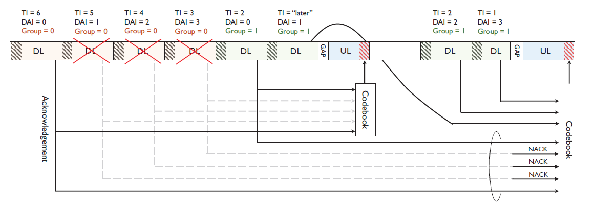
Fig. 1 shows an example of HARQ-ACK feedback operation in the Rel. 16 NR-U standard [23]. In Fig. 1, during the 1st slot, we assume that gNB transmits the corresponding PDSCH belonging to group 0 and UE receives them successfully. Meanwhile, the PDSCHs of the 2nd, the 3rd, and the 4th slots do not arrive at UE due to several reasons such as collision and the weak channel. Nevertheless, gNB expects feedback for four PDSCHs in group 0. In the 7th slot, UE sends a HARQACK feedback for PDSCH group 0. However, this feedback is for PDSCH of the 1st slot only, hence, the decoding of PUCCHs fails because their sizes are mismatched. Moreover, the HARQ-feedback-timing of the PDSCH transmitted in the 6th slot is set to a non-numerical value and the HARQ value will be transmitted at the UL of the next COT after holding. At the next COT, gNB sends PDSCHs belonging to group 1 during the first two slots and the NFI for group 0 without toggling, since gNB does not receive proper HARQ-ACK feedback for group 0. Then, at the end of COT, UE sends a NACK to the PDSCH belonging to group 0 that gNB did not receive, and the HARQ value of group 1 PDSCH including the PDSCH of the 6th slot that was previously withheld.
C. Radio Link Control Layer
In the NR-U system, the channel access procedure affects not only the media access control (MAC) layer but also the RLC layer timing parameter [24]. Specifically, in the case of RLC unacknowledged mode (RLC UM), if the t-Reassembly value is set to be short, the amount of dropped RLC segmented PDU increases due to channel access procedure and collision. On the other hand, when the t-Reassembly value is set to be long, the amount of RLC service data unit (SDU) to be dropped increases when the receiving buffer size is not large. Therefore, gNB and UE must set the t-Reassembly value appropriately. Furthermore, gNB can adjust the UL slot portion by considering the statistics of the packet dropped rate. Compared to RLC UM, the RLC acknowledged mode (RLC AM) supports the ARQ feedback mechanism to ensure reliable packet delivery. Therefore, the PDU status message is periodically sent by UE to indicate the current status of the RLC PDUs received at UE. Specifically, gNB can request UE to send the current PDU status via transmitting a poll.
To regulate the frequent current PDU status transmissions, gNB and UE utilize the t-PollRetransmit and t-StatusProhibit timers as follows. Firstly, the t-PollRetransmit timer is used by gNB AM RLC entity to retransmit a poll. If the t-PollRetransmit timer expires, gNB sends a poll when the transmission and retransmission buffers are empty or when the window is stalled. In this case, gNB includes either the highest segment number that has been submitted for retransmission or any RLC SDU that has not been positively acknowledged in the polling. Secondly, the t-StatusProhibit timer is used by UE AM RLC entity to prohibit the transmission of a STATUS PDU. Consequently, these timers can have a significant impact on the system throughput and latency. For instance, due to the channel access procedure and MCOT, it would be beneficial to control the timers and allocate the UL portion to send the RLC PDU status.
IV. PERFORMANCE EVALUATION
In this section, we present simulation results obtained using the Matlab 5G toolbox, illustrating the effect of different value type, and the RLC layer timing parameters, on the performance of NR-U in the presence of Wi-Fi. To account for channel estimation and feedback, we consider the channel quality indicator (CQI) based on TDD channel reciprocity. We also assume that each resource block (RB) has one value randomly chosen from the maximum CQI values based on the initial configuration of the distance between gNB and UE. We do not consider the hidden node phenomenon in our simulations. Moreover, we assume that Wi-Fi and NR-U nodes confirm channel occupancy based on the minimum remaining time (defer duration + remaining backoff number × 9) rather than energy detection. This means that during contention for channel access, the node with the minimum remaining time wins the contention, and in case of a tie between nodes, it is assumed that collision occurs, and the window size is increased. Regarding data decoding, we assume a block error rate (BLER) of 10%, and the ACK/ NACK is determined based on this probability. We also assume an on-off traffic model for the application layer. Unless stated otherwise, the simulation assumptions used in this article are summarized in Table I.
Table I
| Parameter | Value |
|---|---|
| Wi-Fi System | |
| AP number | 1–8 |
| Header length | 128 bits |
| Acknowledgment (ACK ) | 240 bits |
| Request to send (RTS) | 288 bits |
| Clear to send (CTS) | 352 bits |
| Short inter-frame spacing (SIFS) | [TeX:] $$16 \mu \mathrm{s}$$ |
| Priority class | 1,2,3 |
| NR-U System | |
| gNB/UE number | 1/1 |
| DL/UL bandwidth | 20 MHz |
| Subcarrier spacing (SCS) | 15 kHz, 30 kHz |
| gNB/UE antenna number | 1 |
| Resource block (RB) number | 106 (for 15 kHz), 51 (for 30 kHz) |
| PDSCH/PUSCH mapping type | Type A/Type B |
| HARQ codebook Type | Type 2 |
| COT sharing | Enabled (gNB initiated COT) |
| [TeX:] $$K_0$$ | 0 slot |
| [TeX:] $$K_1$$ | minimum 1 slot |
| [TeX:] $$K_2$$ | minimum 0 slot |
A. Effect of the Switching Pattern on the Latency and Throughput
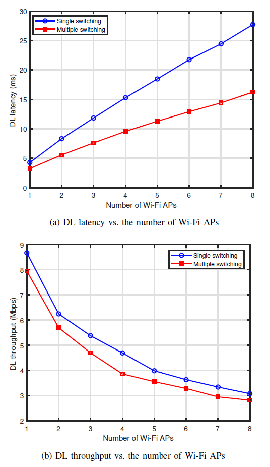
Fig. 2 compares the DL system performance with a corresponding DL/UL slot configuration pattern (single and multiple switching). We assume that SCS is 30 kHz, the number of multiple switches is 2 and the access priority of Wi- Fi is arbitrarily selected from 1 to 3 without hidden nodes under the carrier sense multiple access with collision avoidance (CSMA/CA) approach. Fig. 2 shows that as the number of Wi-Fi access points (AP) increases, gNB is subject to stiff competition for channel access and it is less likely to occupy the channel. Hence, the DL latency increases while the DL throughput decreases. We can observe from Fig. 2 that there is a trade-off between the DL latency and throughput. For example, single switching attains higher DL throughput at the cost of higher latency and the reverse is true for multiple switching. Moreover, substituting single switching with multiple switching leads to a decrease in latency by 35.7% and 40.6% and a decrease in throughput by 12.7% and 9.6% for 3 APs and 6 APs, respectively. Therefore, it is necessary to determine DL/UL slot format and schedule DL/UL transmission, while considering the traffic status, throughput/latency requirement, CQI, PUCCH overhead, RLC status protocol data unit (PDU), and others.
B. Influence of the HARQ Feedback Value Type on the Latency and Retransmission Rate
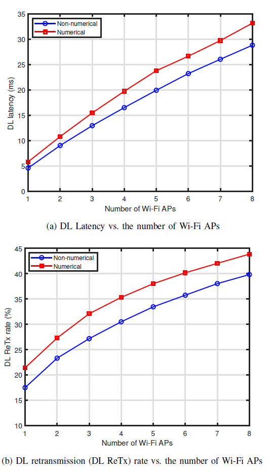
Fig. 3 presents the DL system performance for a corresponding HARQ feedback value type versus the number of Wi-Fi APs. We set the number of switching points to 1 and consider similar assumptions stated in the evaluation for Fig. 2. From Fig. 3, it can be seen that as the number of Wi-Fi APs increases, the DL latency and retransmission rate increase. Additionally, the DL latency and retransmission rate are higher when the numerical value is used compared to the case when the non-numerical value is used. When the access priority of Wi-Fi is varied from 1 to 2 and the backoff value is 0, the CAT2-LBT channel access procedure performed during DL/UL switching fails which prompts retransmission and leads to increased latency. Therefore, by employing the inapplicable HARQ feedback value concept, the DL latency and retransmission rate can be reduced. For instance, the DL latency decreases by 16.3% and 12.9% while the retransmission rate decreases by 4.9% and 4.5% for 3 APs and 6 APs, respectively, when the non-numerical value is used.
C. Impact of the t-Reassembly Value on the Packet Dropped Rate
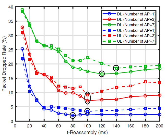
Fig. 4 shows the comparison of the DL/UL packet drop rate with the t-Reassembly value for the varying number of Wi-Fi APs such as 1, 3, and 7. Three observations can be drawn from Fig. 4. Firstly, as the number of APs varies, the DL/UL packet drop rate initially decreases rapidly and gradually increases with higher t-Reassembly values. For example, when the number of Wi-Fi APs is 3 and the t-Reassembly value is varied from 10 ms to 100 ms, the packet dropped rate decreases by 70% and 78% for UL and DL respectively. This performance justifies the discussions made earlier. Secondly, as the number of APs increases, so does the packet drop rate. This is because the probability of occupying the channel decreases, resulting in the packet being dropped as it is less likely to come in t-Reassembly. Lastly, since each scenario (varying number of APs) presents a different optimal DL/UL t-Reassembly value (marked with a black circle), it is therefore important for gNB to set this value well based on the statistics of the channel situation with feedback from UE.
V. CONCLUSION
In this article, we provided an overview of the design mechanisms for LTE-LAA and NR-U technologies. We further investigated the impact of the switching pattern, the feedback value type, and the timing parameters as enablers of NR-U scheduling. We also presented simulation results to illustrate the performance of NR-U for varying configurations of selected design features. It has been shown that appropriate configurations improve NR-U performance in terms of latency and reliability as well as attaining fair coexistence between NR-U systems with other RATs operating in unlicensed bands. To this end, we hope that our findings will trigger further research interests toward achieving a highly reliable and lowlatency- enabled next generation of NR-U.
Biography
Julius Ssimbwa

Julius Ssimbwa received his B.S. degree in Telecommunications Engineering from Makerere University, Kampala, Uganda, in 2016, and his M.S. degree in Electrical Engineering from Korea University, Seoul, Korea, in 2021, where he is currently pursuing a Ph.D. degree with the School of Electrical Engineering. He was an O&M Engineer at Huawei Technologies (Uganda) from 2015 to 2016. In 2017, he joined the I-Engineering group (Uganda) as an O&M Supervisor. His current research interests are signal processing, radio resource management, and multiple antenna technologies.
Biography
Seok-Hyun Yoon

Seok-Hyun Yoon received his B.S. degree in Computer Science and Communication Engineering from Korea University, Seoul, South Korea in 2017, where he is pursuing a Ph.D. degree with the School of Electrical Engineering. In 2022, he visited Tufts University, Medford, MA, USA, to conduct collaborative research. His research interests include mmWave/THz beamforming, intelligent reflecting surfaces (IRS), and full-duplex communication.
Biography
Yeongrok Lee

Yeongrok Lee received his B.S. and Ph.D. degrees in Electrical Engineering from Korea University, Seoul, in 2016 and 2023, respectively. Since March 2023, he has been with Samsung Electronics. His research interests include wireless LAN standards, software-defined radio, vehicular communication, and machine learning in communications and networks.
Biography
Young-Chai Ko

Young-Chai Ko received his B.Sc. degree in Electrical and Telecommunication Engineering from Hanyang University, Seoul, Korea, and his M.S.E.E. and Ph.D. degrees in Electrical Engineering from the University of Minnesota, Minneapolis, MN in 1999 and 2001, respectively. He was with Novatel Wireless as a research scientist from January 2001 to March 2001. In March 2001, he joined Texas Instruments, Inc., wireless center, San Diego, CA, as a Senior Engineer. He is now with the School of Electrical Engineering at Korea University as a Professor. His current research interests include the design and evaluation of multi-user cellular systems, MODEM architecture, mmWave, and THz wireless systems.
References
- 1 FCC 18-295, "Unlicensed use of the 6 GHz band. Notice of proposed rulemaking ," Oct. 2018. Accessed: Aug. 30, 2002. (Online). Available: https://docs.fcc.gov/public/attachments/DOC-354364A1.pdf.custom:[[[https://docs.fcc.gov/public/attachments/DOC-354364A1.pdf]]]
- 2 E. Khorov, I. Levitsky, and I. F. Akyildiz, "Current status and directions of IEEE 802.11be, the future Wi-Fi 7," IEEE Access, vol. 8, pp. 88664-88688, 2020.doi:[[[10.1109/ACCESS.2020.2993448]]]
- 3 3GPP TR 36.889 V13.0.0 3, "3rd generation partnership project; technical specification group radio access network; study on licensed-assisted access to unlicensed spectrum," Tech. Rep., Jun. 2015.custom:[[[-]]]
- 4 3GPP TR 38.889 V16.0.0, "3rd generation partnership project; technical specification group radio access network; study on NR-based access to unlicensed spectrum," Tech. Rep., Dec. 2018.custom:[[[-]]]
- 5 3GPP TS 38.300 V17.3.0, "NR; NR and NG-RAN overall description; stage 2," Tech. Rep., Dec. 2022.custom:[[[-]]]
- 6 B. Zheng et al., "Design of multi-carrier LBT for LAA& WiFi coexistence in unlicensed spectrum," IEEE Netw., vol. 34, no. 1, pp. 76-83, Jan. 2020.doi:[[[10.1109/MNET.2019.1900172]]]
- 7 A. K. K. Chatzikokolakis, P. Spapis, and N. Alonistioti, "Toward spectrum sharing: Opportunities and technical enabler," IEEE Commun. Mag., vol. 53, no. 7, pp. 26-33, 2015.doi:[[[10.1109/MCOM.2015.7158262]]]
- 8 E. Perahia, "TGax coexistence assurance document, doc.: IEEE 802.11-16/1348r7," Nov. 2019. Accessed: Sep. 11, 2002. (Online). Available: https://mentor.ieee.org/802.11/dcn/16/ 11-16-1348-07-00ax-coexistence-assurance.docx.custom:[[[https://mentor.ieee.org/802.11/dcn/16/11-16-1348-07-00ax-coexistence-assurance.docx]]]
- 9 S. Lagen et al., "New radio beam-based access to unlicensed spectrum: Design challenges and solutions," IEEE Commun. Surveys Tut., vol. 22, no. 1, pp. 8-37, 2020.doi:[[[10.1109/COMST.2019.2949145]]]
- 10 J. A. G. Naik, J. M. Park, and W. Lehr, "Next generation Wi-Fi and 5G NR-U in the 6 GHz bands: Opportunities and challenges," IEEE Access, vol. 8, pp. 153027-153056, Aug. 2020.doi:[[[10.1109/ACCESS.2020.3016036]]]
- 11 B. K. M. Hirzallah, M. Krunz, and B. Hamzeh, "5G new radio unlicensed: Challenges and evaluation," IEEE Trans. Cogn. Commun. Netw., vol. 7, no. 3, pp. 689-701, Sep. 2021.doi:[[[10.1109/TCCN.2020.3041851]]]
- 12 R. Maldonado, C. Rosa, and K. I. Pedersen, "Latency and reliability analysis of cellular networks in unlicensed spectrum," IEEE Access, vol. 8, pp. 49412-49423, 2020.doi:[[[10.1109/ACCESS.2020.2978032]]]
- 13 B. B. N. Patriciello, S. Lag´ en, and L. Giupponi, "NR-U and IEEE 802.11 technologies coexistence in unlicensed mmWave spectrum: Models and evaluation," IEEE Access, vol. 8, pp. 71254-71271, Apr. 2020.doi:[[[10.1109/ACCESS.2020.2987467]]]
- 14 L. Wang et al., "Joint bandwidth and transmission opportunity allocation for the coexistence between NR-U and WiFi systems in the unlicensed band," IEEE Trans. Veh. Technol., vol. 70, no. 11, pp. 11881-11893, 2021.doi:[[[10.1109/TVT.2021.3116378]]]
- 15 H. Bao, Y . Huo, X. Dong, and C. Huang, "Joint time and power allocation for 5G NR unlicensed systems," IEEE Trans. Wireless Commun., vol. 20, no. 9, pp. 6195-6209, 2021.doi:[[[10.1109/TWC.2021.3072553]]]
- 16 RP-190706, "NR-based access to unlicensed spectrum," 3GPP TSG RAN Meeting #83, Tech. Rep., Mar. 2019.doi:[[[10.1109/COMST.2019.2949145]]]
- 17 3GPP TS 37.213 V16.3.0, "3rd generation partnership project; technical specification group radio access network; physical layer procedures for shared spectrum channel access," Tech. Rep., Sep. 2020.custom:[[[-]]]
- 18 R1-1909249, "Wideband operation for NR-U," 3GPP TSG RAN WG1 Meeting #98, Tech. Rep., Aug. 2019.custom:[[[-]]]
- 19 3GPP TR 38.808 V17.0.0, "Study on supporting NR from 52.6 GHz to 71 GHz," Tech. Rep., Mar. 2021.custom:[[[-]]]
- 20 3GPP TS 37.213 V17.4.0, "Physical layer procedures for shared spectrum channel access," Tech. Rep., Mar. 2021.custom:[[[-]]]
- 21 R1-2202685, "FL summary of channel access mechanism for 52.6 GHz-71 GHz Band," 3GPP TSG RAN WG1 Meeting #108, Tech. Rep., Feb. 2022.custom:[[[-]]]
- 22 3GPP TS 38.213 V16.12.0, "Physical layer procedures for control," Tech. Rep., Jan. 2023.custom:[[[-]]]
- 23 E. Dahlman, S. Parkvall, and J. Skold, 5G NR: The Next Generation Wireless Access Technology. Academic Press, 2020.custom:[[[-]]]
- 24 3GPP TS 38.322 V16.3.0, "Radio link control (RLC) protocol specification," Tech. Rep., Aug. 2022.custom:[[[-]]]